Renforcement et inspection de dalles en béton coulées sur place
Dans un projet de construction résidentielle, avant la construction de la couche d'amortissement et de la couche de surface, des fissures de moins de 0,3 mm ont été décelées dans la dalle en béton coulé sur place, ainsi qu'une fuite après injection d'eau. Après carottage, il a été constaté que ces fissures étaient dues à une résistance du béton et à une épaisseur de la dalle non conformes aux exigences de conception.
Dans un projet de construction résidentielle, avant la construction de la couche d'amortissement et de la couche de surface, des fissures inférieures à 0,3 mm ont été détectées dans la dalle en béton coulé sur place, ainsi qu'une fuite après injection d'eau. Après carottage, il a été constaté que ces fissures étaient dues à une résistance du béton et à une épaisseur de dalle non conformes aux exigences de conception.
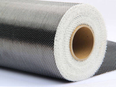
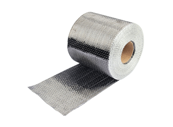
Collage de tissu en fibre de carbone (PRFC)
Le principe de collage du PRFC est le même que celui des plaques d'acier. Le PRFC est utilisé à la place des plaques d'acier pour coller le PRFC à la surface des éléments en béton, ce qui permet une meilleure adhérence des éléments en béton et de leur résistance à la corrosion. La fibre de carbone présente les avantages d'une résistance élevée, d'une résistance à la corrosion, d'une mise en œuvre aisée et d'une taille pratiquement inchangée après renforcement, ce qui explique son utilisation fréquente pour le renforcement de divers éléments en béton.
Injection de fissures
1. Inspection des fissures
2. Traitement des fissures
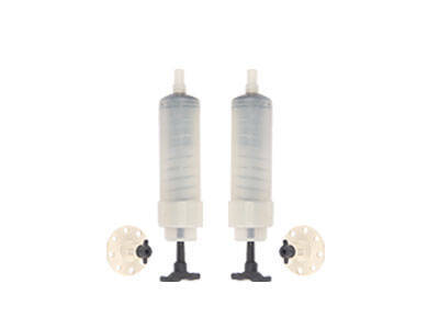
3. Intégration de la buse de coulée de colle
4. Scellement des fissures
5. Vérification de l'étanchéité
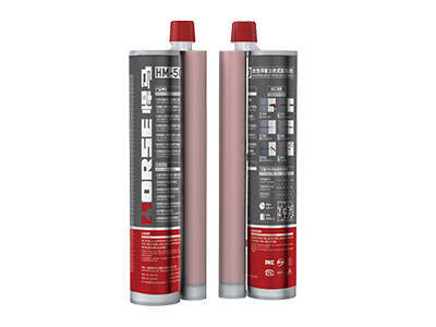
6. Préparation de la colle de coulée
7. Coulage de la colle
8. Conservation
9. Examen et essai
Traitement de l'épaisseur du sol
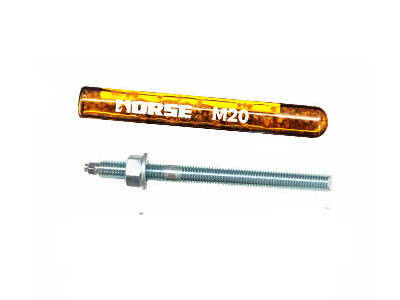
Ancrages après installation
1. Percer le trou au diamètre et à la profondeur requis. Le diamètre doit être adapté à la taille de la cheville.
2. Nettoyer le trou à la soufflette, en commençant par le fond du trou, puis soigneusement à la brosse métallique. Après le brossage, nettoyer à nouveau le trou à la soufflette.
3. Injecter la résine d'ancrage dans le trou, en commençant par le fond, tout en retirant lentement le mélangeur statique. Éviter toute accumulation d'air. Pour les trous profonds, utiliser une rallonge.
4. Insérer la cheville dans le trou percé par un mouvement rotatif. Un peu de colle doit sortir du trou.
5. Pendant le temps de durcissement de la résine, l’ancrage ne doit pas être déplacé ni chargé.
Essai de déflexion du plancher et de largeur de fissure
1) Échantillonnage des composants d'essai. La dalle de plancher coulée en place a été renforcée par collage de fibres de carbone, insertion d'armatures à moment négatif et laminage du plancher. Par conséquent, un échantillonnage aléatoire est effectué pour l'essai de charge statique.
2) Charge d'essai. L'essai ne teste que la déflexion et la largeur de fissure du plancher. Conformément à la norme GB 5015292 relative aux méthodes d'essai des structures en béton, la charge d'essai est déterminée en fonction de la charge limite de service normal.
La valeur de charge maximale de cet essai correspond à la charge utile uniforme du plancher et à la charge du plancher en briques. La valeur standard pour la charge utile uniforme du plancher est de 2,0 kN/m², la charge pour le plancher en briques est de 0,7 kN/m² et la valeur de charge maximale totale est de 2,7 kN/m².
3) Instruments de mesure et équipement de chargement. L'instrument de mesure est équipé d'un appareil de mesure de percentile 10 mm et 50 mm, d'un appareil de pesée, d'une règle en acier et d'un microscope à échelle 40, ainsi que de 5 400 briques d'argile pleines. Après pesée sur site, 100 briques ont été pesées : le poids moyen de chaque brique est de 0,0225 kN et le poids total est de 121,5 kN.
4) Essais de chargement et de déchargement. L'essai a été réalisé en six étapes. À chaque étape, la durée de chargement est de 10 minutes. La déformation de chaque pièce est mesurée et la première charge est ajoutée. Toutes les valeurs de charge d'essai sont additionnées, la durée de chargement étant d'au moins 30 minutes. Lors de l'essai sur site, afin de tester les caractéristiques de déformation de la plaque, la durée de la charge d'essai maximale peut être portée à 60 minutes, voire à plus de 12 heures.
La classification de déchargement est déterminée en fonction de la déformation de la plaque. Trois déchargements, deux déchargements, un déchargement. La durée de chaque déchargement est de 10 minutes. Après le déchargement de toutes les charges, la durée de récupération de la déformation est d'au moins 45 minutes.
5) Mesure de la déformation et de la rupture.
A. Les points de mesure de la flèche sont disposés le long de la flèche maximale des deux directions de portée du plancher, et les points de mesure de la déformation d'appui sont disposés au milieu de chaque côté du plancher. Pour une plaque de taille standard, cinq points de mesure peuvent être disposés ; pour une plaque d'une portée d'au moins 6 m, des points de mesure supplémentaires sont placés à la position quatre points dans la direction de la grande portée.
B. Installation des instruments de mesure, mise en place des supports sur le plancher et les supports doivent rester indépendants. Le comparateur à cadran pour la mesure de la déformation est installé sur le support et numéroté séparément. Ne plus déplacer l'instrument après son installation.
C. Mesure de la déformation : avant le chargement, relever la lecture initiale de chaque comparateur à cadran ; Après chaque phase de chargement, mesurer la déformation de chaque composant. Après chaque phase de déchargement, mesurer la déformation résiduelle de chaque composant.
D. Observation des fissures : avant chaque essai de chargement, observer la présence de fissures à la base du panneau et consigner ces données. Pendant le chargement, surveiller attentivement la déformation du plancher, observer attentivement la présence ou l'apparition de fissures à la base du panneau et consigner ces données. La largeur de la fracture a été observée au microscope étalonné 40 fois.
Résultat de l'essai
Un essai de charge statique à court terme a été réalisé. La déformation à mi-portée de la dalle sous charge d'essai, la flèche à mi-portée et à courte portée mesurée après correction et le calcul de la flèche à long terme prenant en compte l'effet à long terme de la charge sont pris en compte. En combinant les exigences limites de l'état limite de service normal dans le Code de conception des structures en béton, il est déterminé si le plancher peut répondre aux exigences limites de déformation et de largeur de fissure dans l'état limite de service normal.


